The first test of the servos in the frame

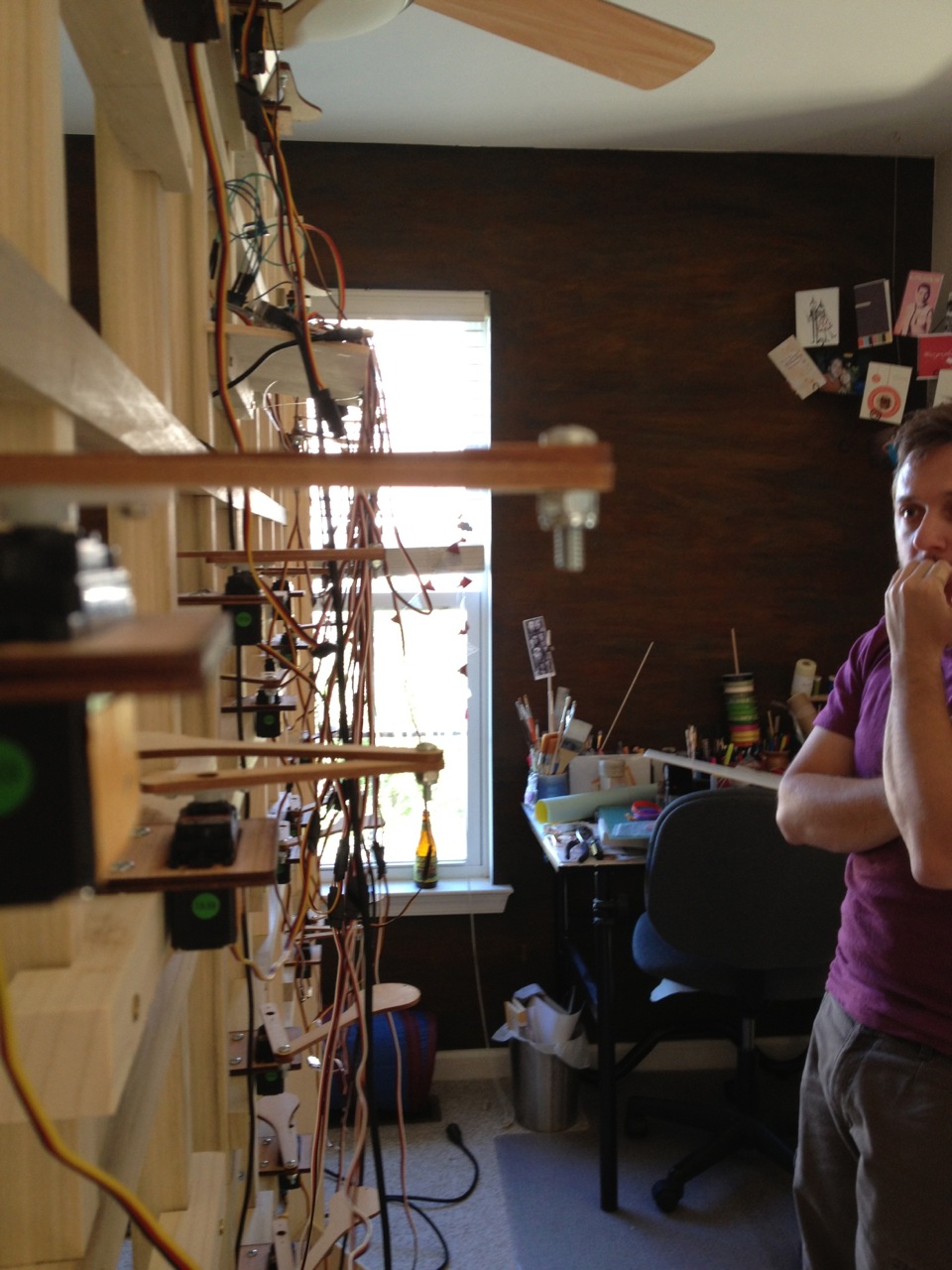
Terrifying. This is my face when I’m terrified.

first-test


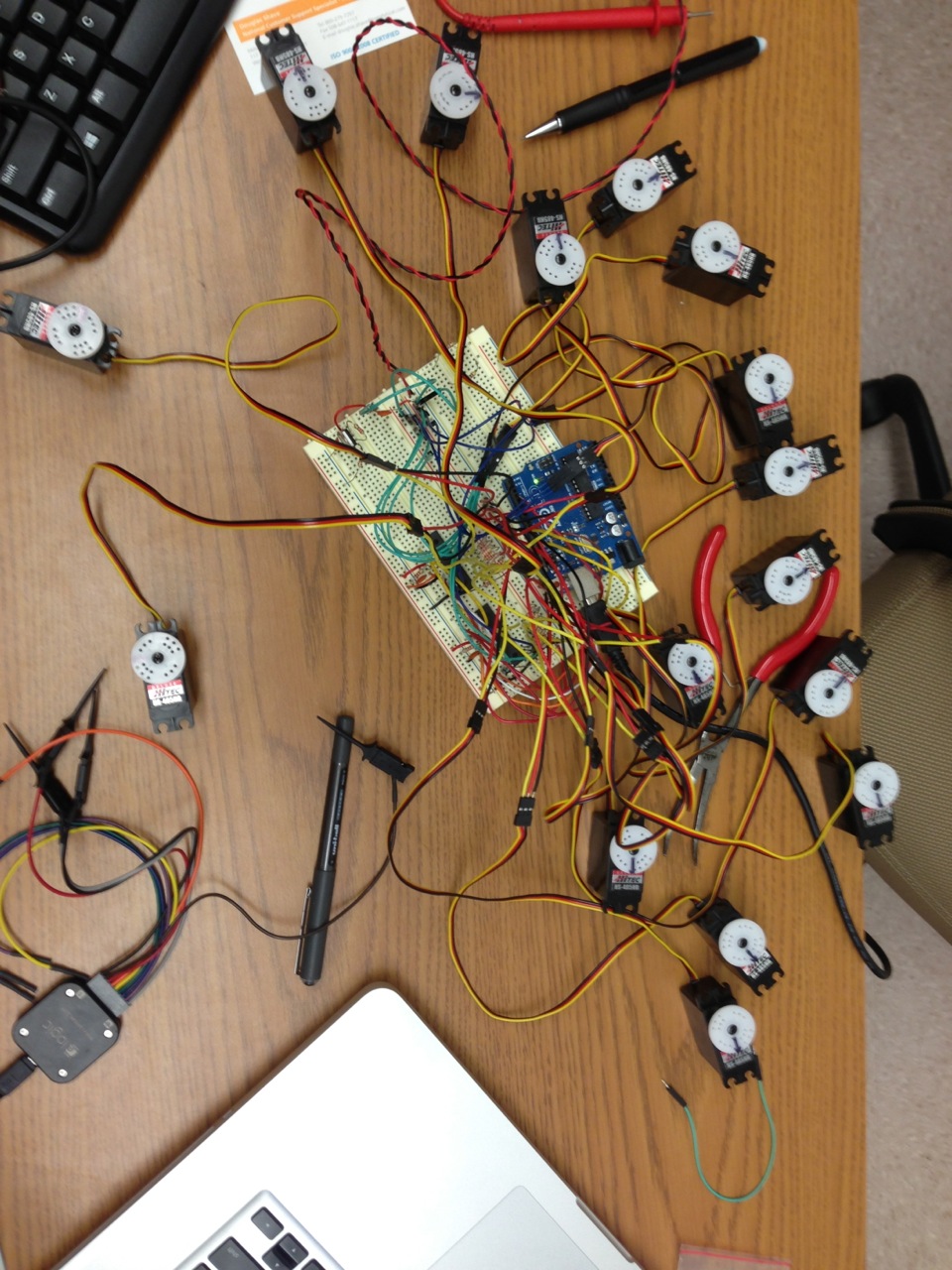
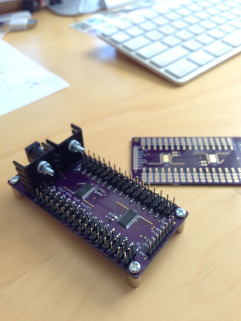
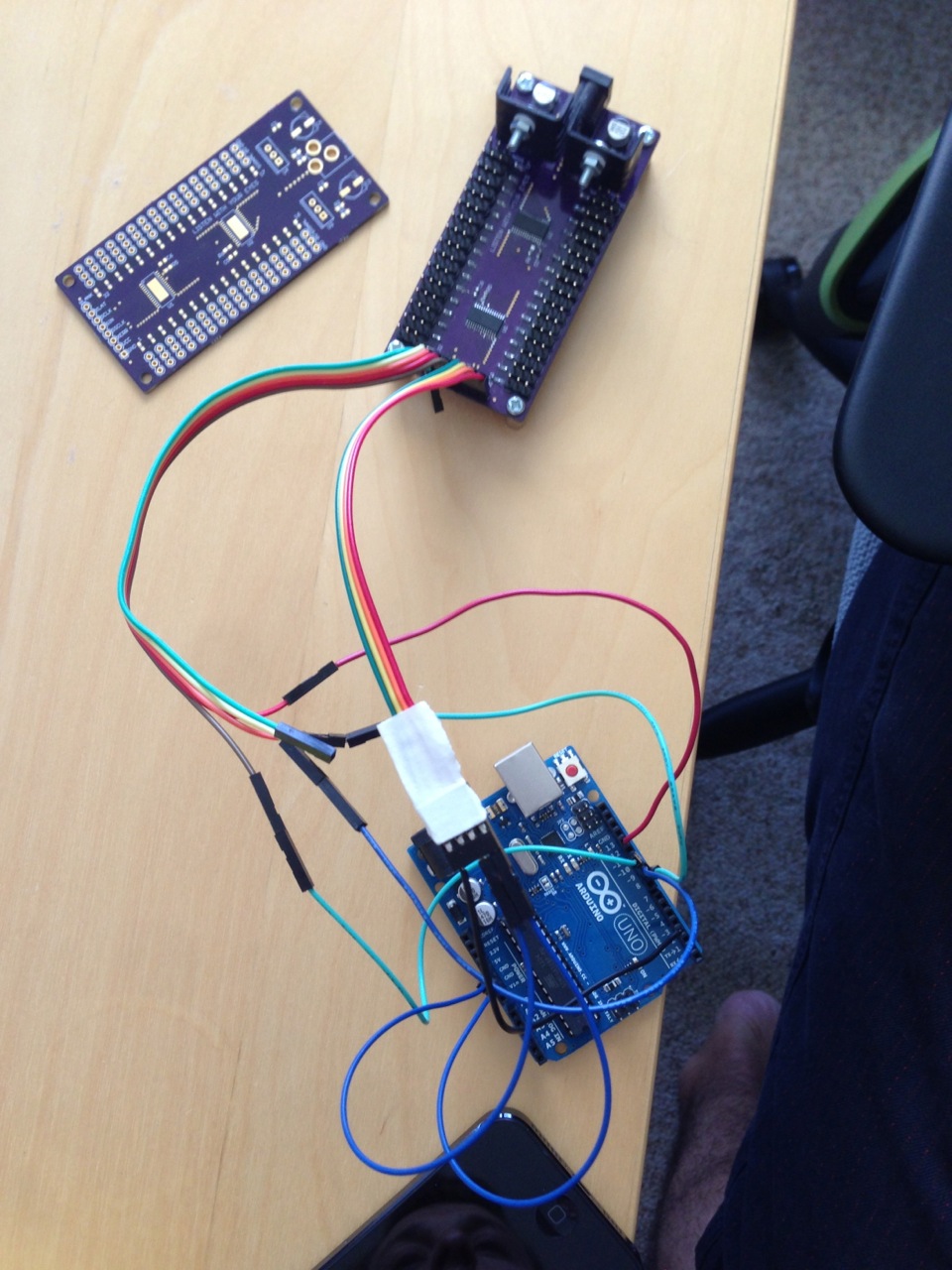
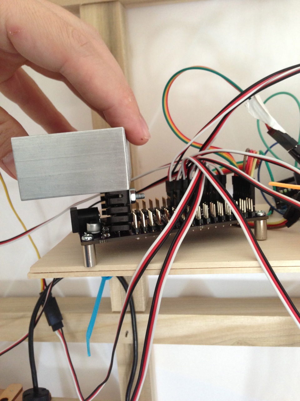
What I learned: electronics with moving parts get very hot, when they get hot they function more poorly, when they function poorly weird inconsistent things happen with movement. After much debugging and trial and error I added a hefty heat sync (attached with an awesome product: Arctic Silver Thermal Adhesive), and eventually I added a small fan as well. This seemed to eliminate many of the “strange” issues with inconsistent movements.
heat-sync

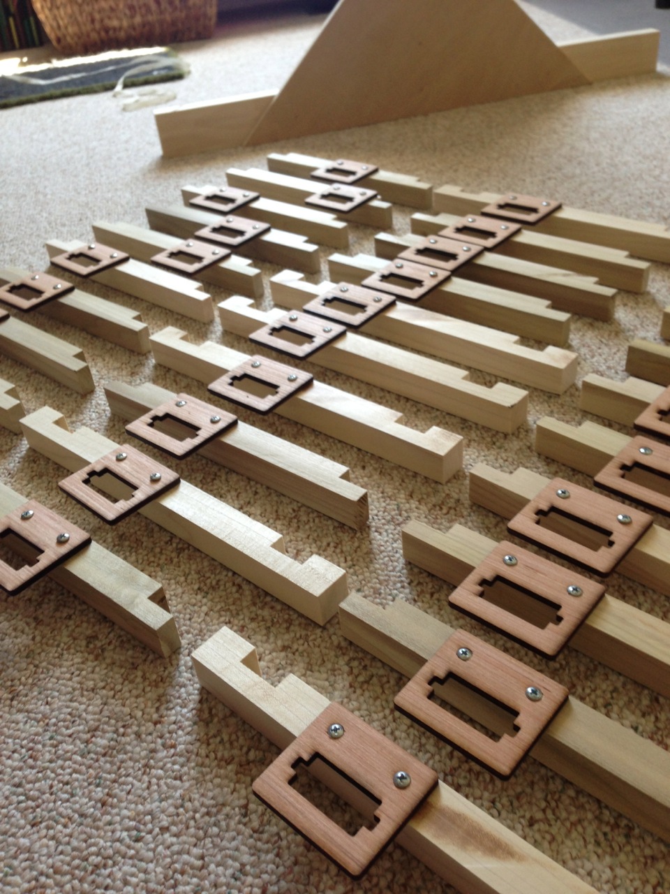
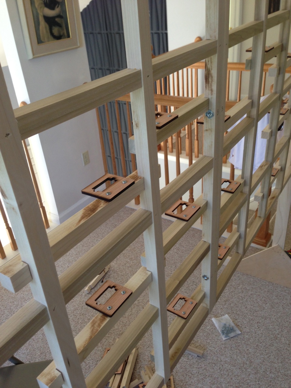
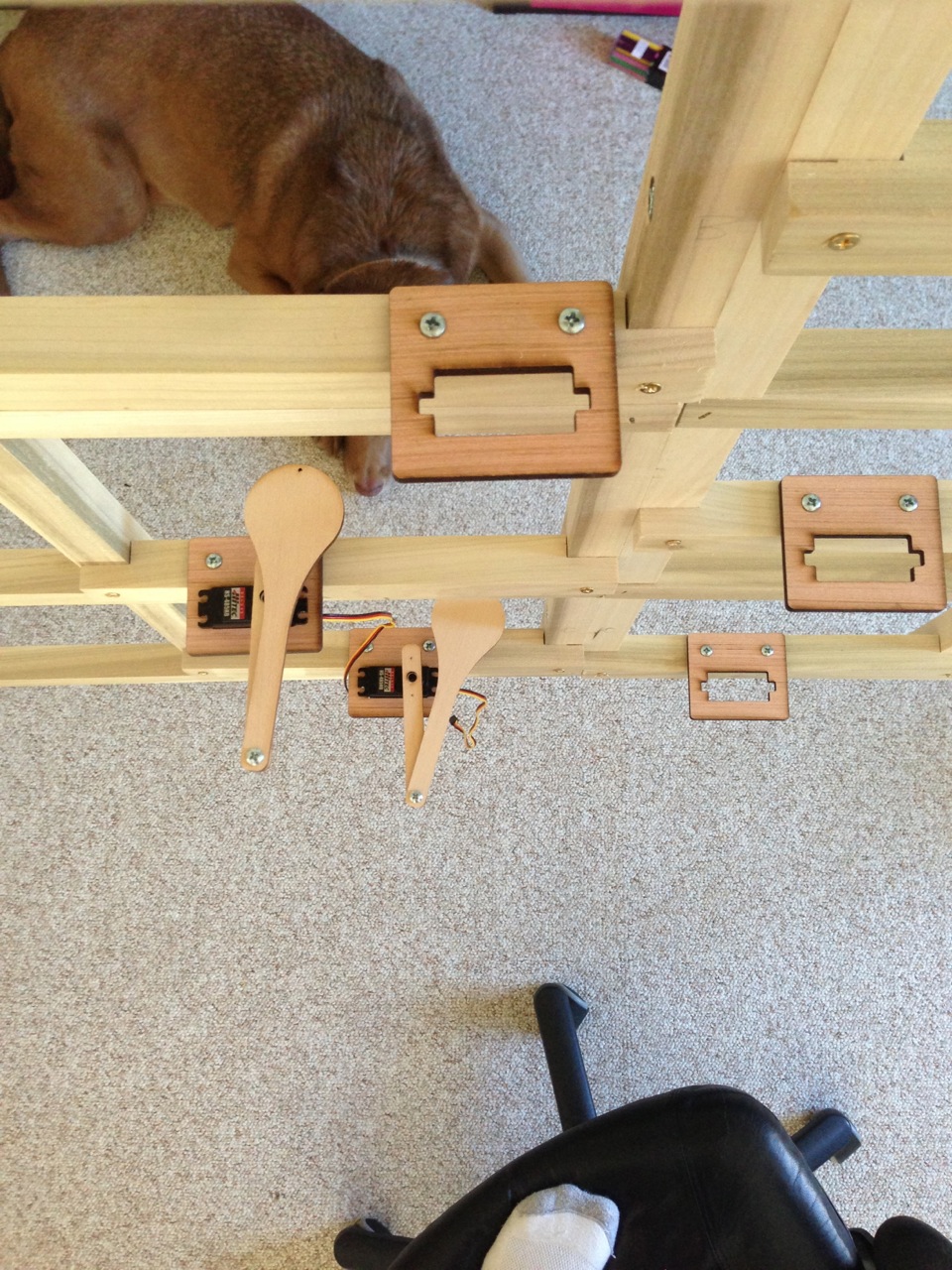
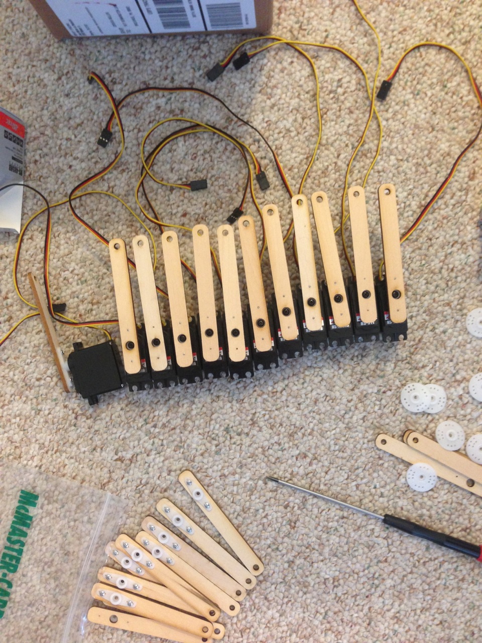
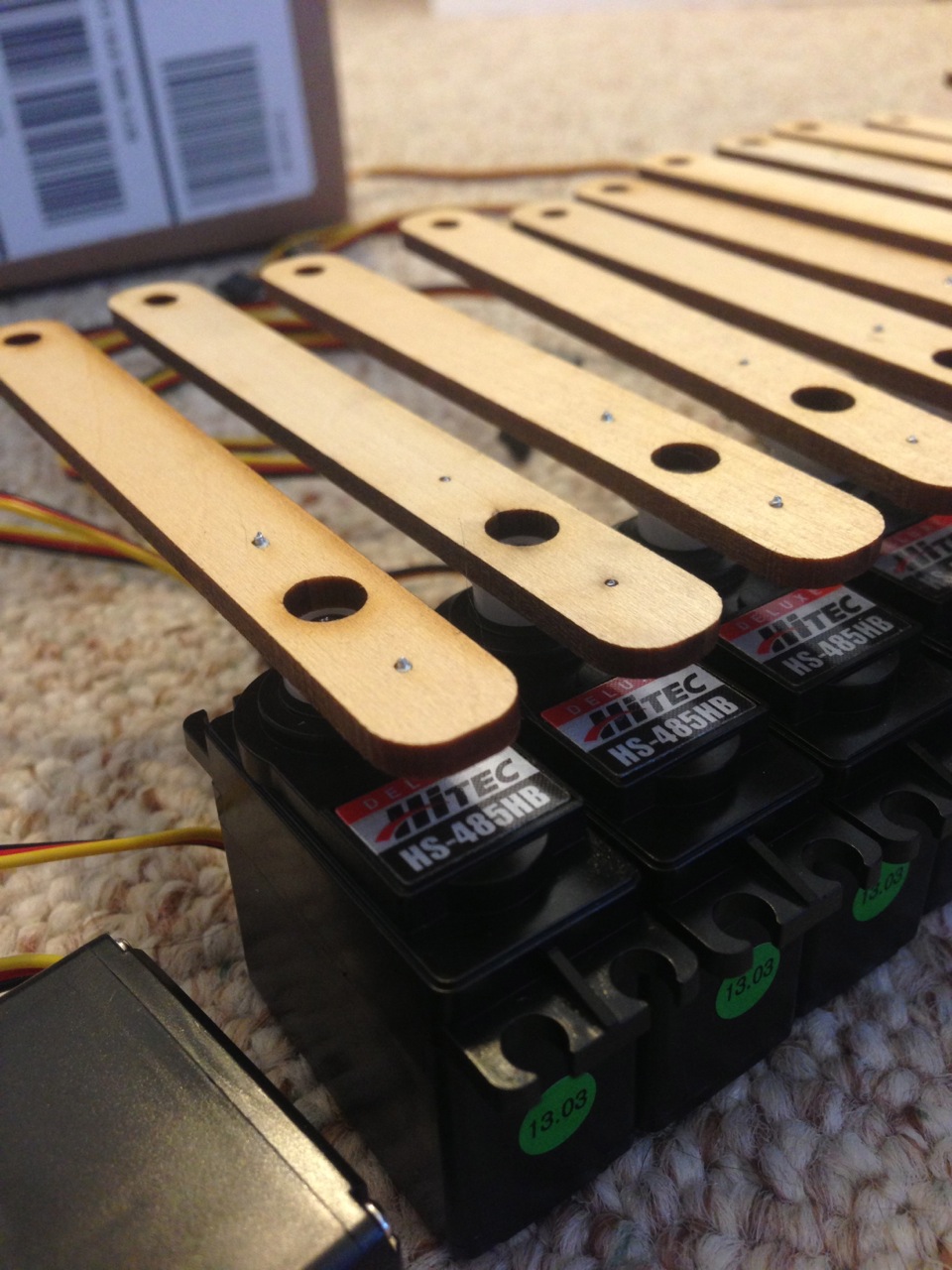
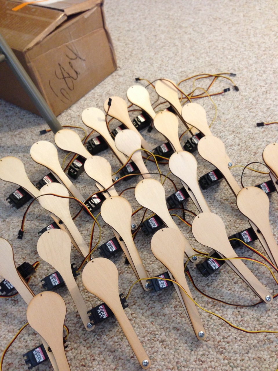
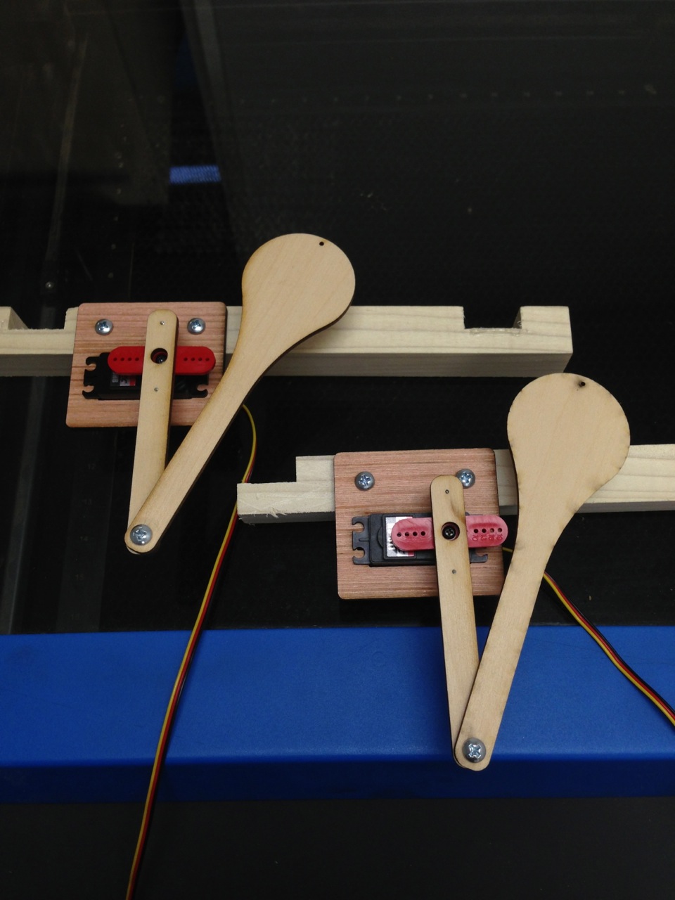
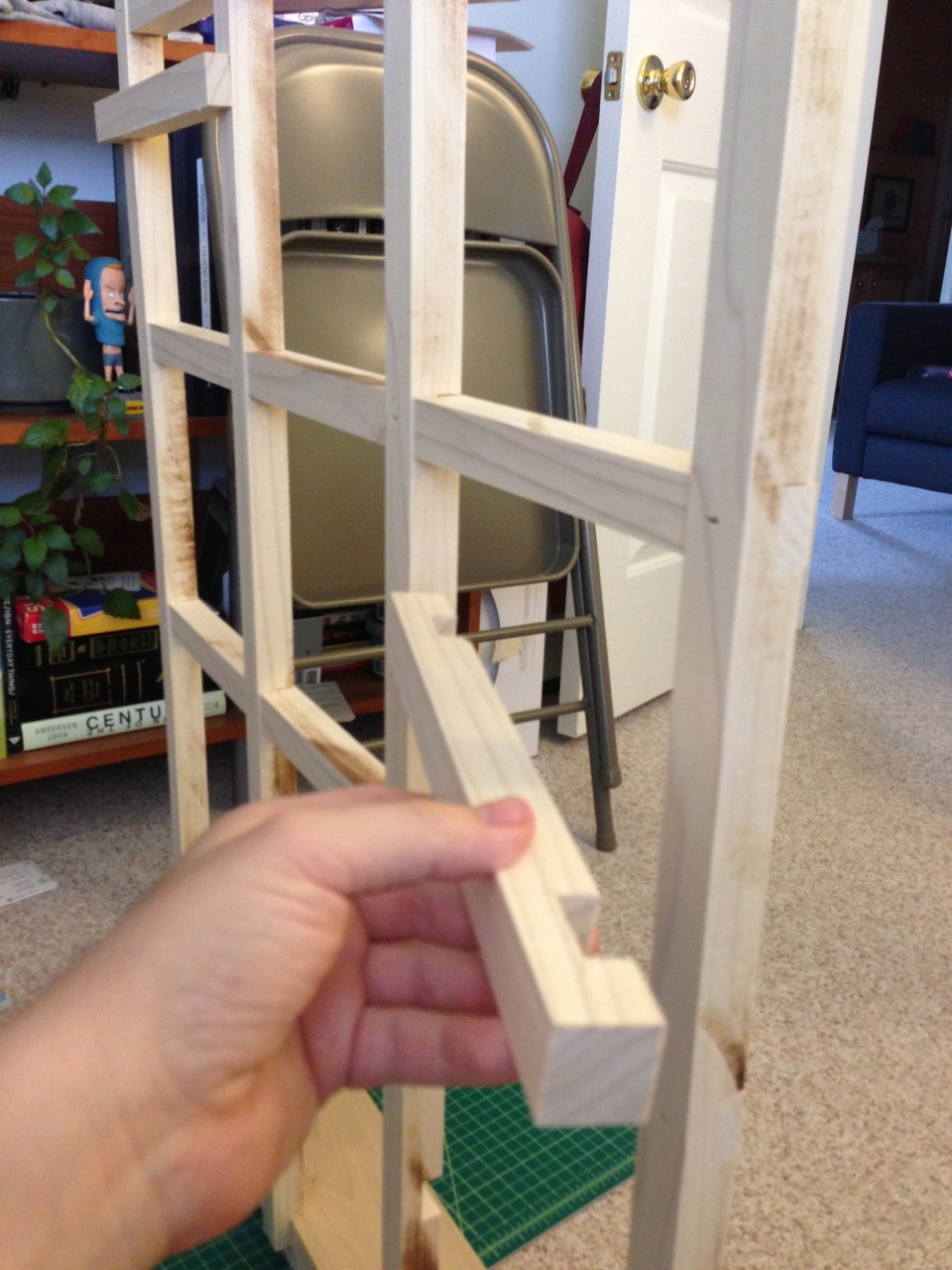
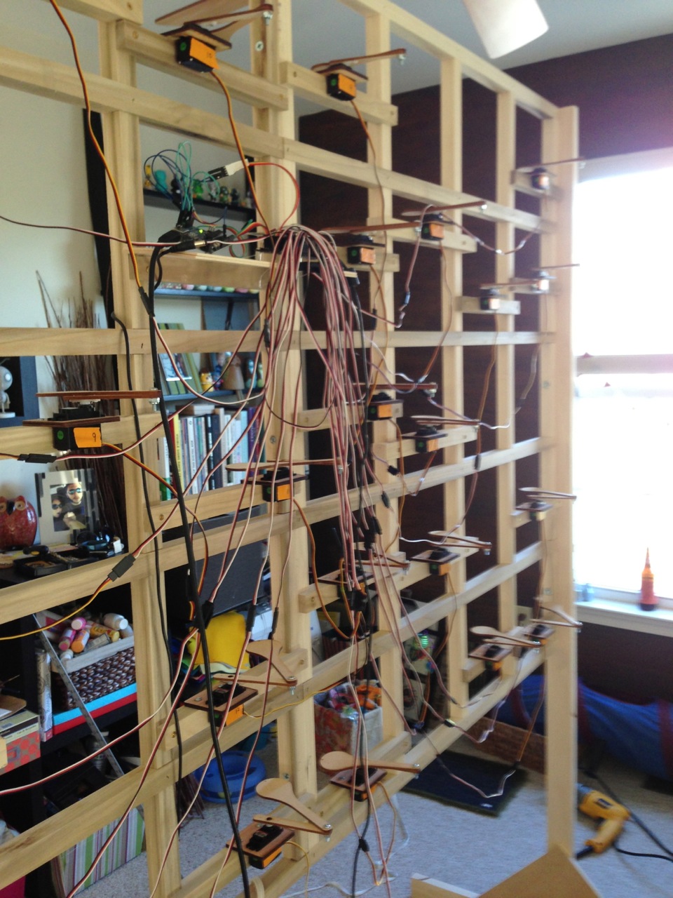
Half of the servos in the frame before the screen was installed:
servos-in-frame


Oh, by the way, it worked:


Leave a Comment

Filed under Uncategorized

The Frame!

With Brian’s expert woodworking assistance, we were able to build a frame that was modular but sturdy, so it can be broken-down and transported. Brian at Lehigh’s woodshop and it’s current location in my home:

frame-assembly frame-assembly2


With the frame assembled, I started building the servo attachment pieces (which were previously laser cut) and attaching the pieces to the frame itself.

servo-holder-assembly servo-holder-attachments servos-in-holders(show above, Piggy who was upset about the installation process, and also my foot in a sock, on a rolling chair that rotates way too freely)


Leave a Comment

Filed under Uncategorized

More than 2 servos…

With the screen and servo attachments figured out, the next step was to figure out how to control (and power!) more than 2 servos. My buddy Ryan is an electrical genius (he’s getting a PHd in Chips, and seems to not have a website), so he said he’d help with a servo controller. The first step was to prototype on a breadboard connected to an arduino and control the servos via tlc5940arduino, an arduino library for the TI TLC5940 16-Channel PWM chip.

multi-servo-test2 multi-servo-test1 multi-servo-test3


A video of the servos running:

At this point I had moved up to the Hitec HS-485HB’s because I needed a bit more power to push the projection screen. And we realized that the servos used more power than what was listed on the data sheet, and consequently they need a larger heat sync and a beefier power supply. More on this later, but we were able to get the servos moving in isolation, so that’s a step forward.

The next step in the process was to build the servo arm with the laser cut servo arms

servo-assembly servo-attachments servo-attachments2 servo-army

Eventually we moved off the breadboard to a custom controller than Ryan engineered, which would power and control the servos just as the breadboard did.

servo-board servo-board2 servo-board-arduino

Leave a Comment

Filed under Uncategorized

Scaling Up

Prototype for the frame, surface, and two servo motors are complete. So the next step is to move out of the prototype phase and figure out how to scale the piece up to full size. Everything needs to be mass-produced, and the pieces can’t be held on with hot glue anymore. Brian helped again by laser cutting servo arms and servo holders.

laser-armslaser-holder

When assembled and screwed into the servo top attachment, the servo unit looks like:
assembled-arms

And here’s the real servo arm pushing the projection screen… it’s beautiful!


Leave a Comment

Filed under Uncategorized

Small Frame Test

With the projection surface finalized, the next step was planning the frame itself. The amazing Brian Slocum from Lehigh University’s Design Labs was incredibly helpful in this process. We decided a basic scale for the frame (which later changed a bit), and Brian suggested that the servo attachments should be modular so they could be repositioned to align with the projections surface.

whiteboard

This was later scaled down to 8 columns rather than 10. The split in the middle would allow for the piece to be disassembled and transported.

The next step was to create a miniature version of the piece for further prototyping

frame-prototype

The “servo” would be attached to the modular wood piece, which would be secured to the frame itself.

thread-on-proto


Thread prototype on mini-frame.

thread-push

Which pushes the spandex, which pushes the pushes the foam board. Once that functioned correctly, I moved to an actual servo. I used the HS-311 from Hitec because it was inexpensive and had a reasonable amount of power. Powered and controlled with an arduino:

first-servo-test


Servo test with rigid connection:

Servo Test with joint connection:

The view from in front of the foam projection surface:


Leave a Comment

Filed under Uncategorized